Shading
Page PV-Modules: Shading
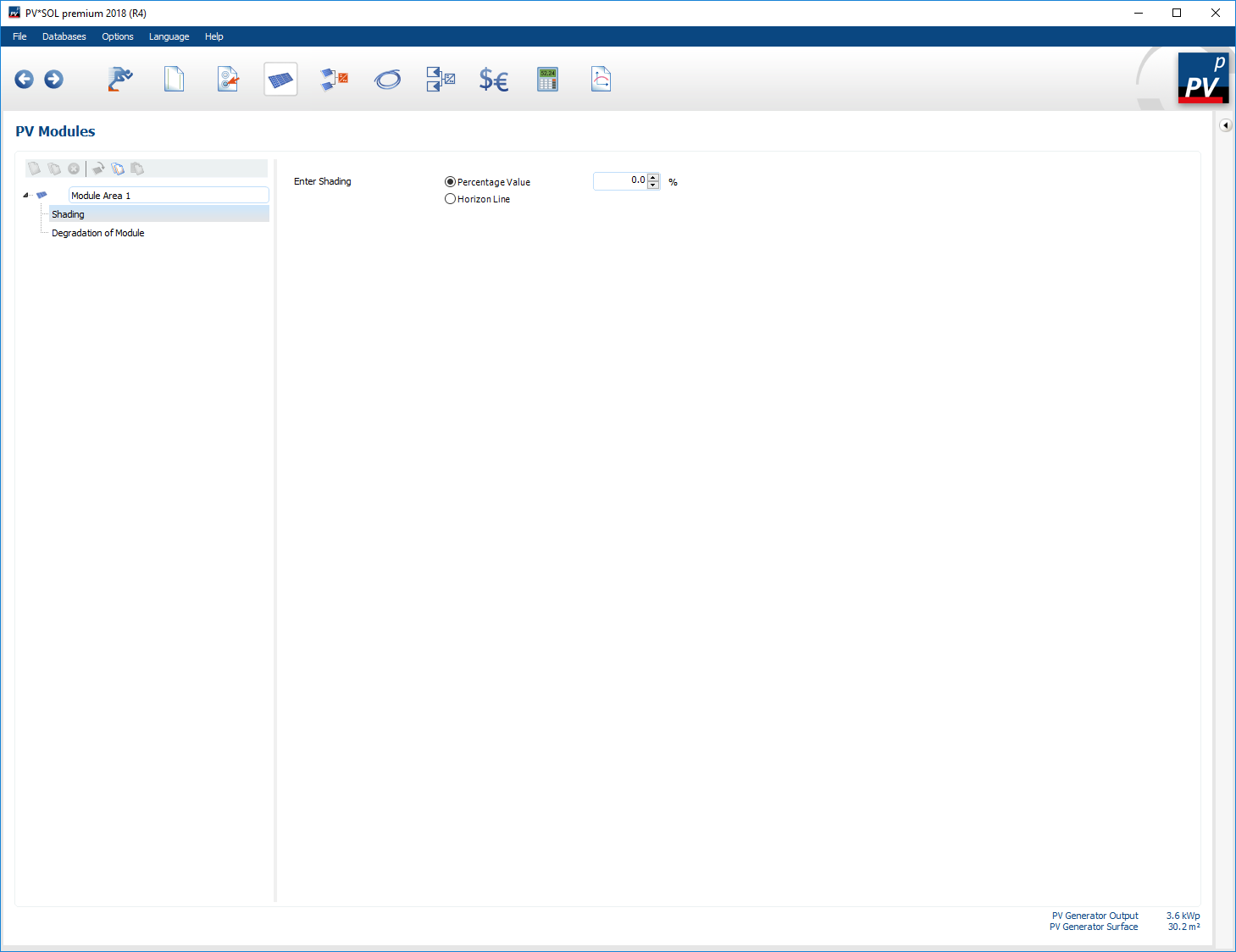
In the subitem shading information on the shading losses of a module surface can be found. The shading losses reduce the irradiation on the module surface, whereby direct and diffuse irradiation are equally reduced. There are two options for entering the shading losses:
- Percentual value (Shading losses on an annual average)
- Horizon line
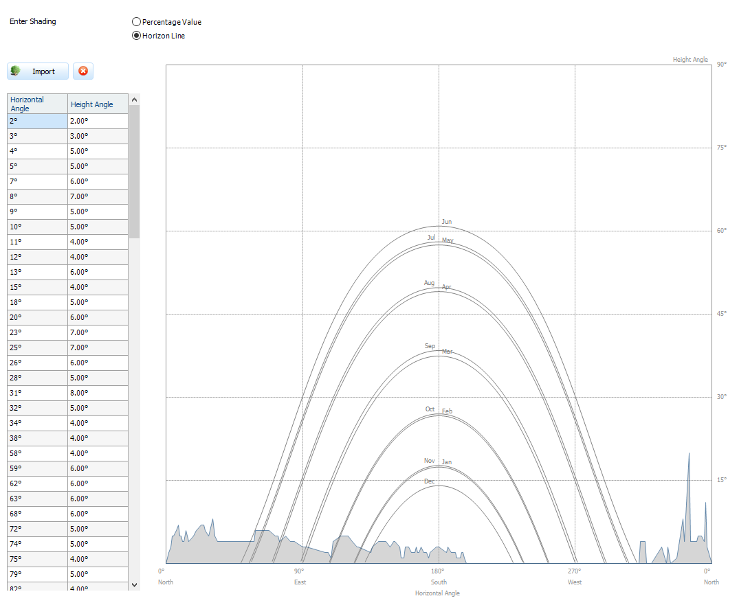
Horizon line
A horizon line is defined by entering it in the table or by clicking on it in the diagram. A point of the horizon consists of the horizontal angle (azimuth) and from the corresponding elevation angle. To create a horizon line, the points of the horizon can be entered or complete horizon lines can be imported using the button
 . The file to be imported must be in *.hor format.
*.hor-Format: If you want to create your own skyline file, the file must be in the following format:
-
2 columns separated by a space
-
In the first column are the horizontal angles, from -180 to 179°
Horizontal angle *.hor format in degrees (°) Horizontal angle in PV*SOL in degrees (°) -180 0 - North -90 90 - East 0 180 - South 90 270 - West -
In the second column the elevation angle, from 0 to 90°
-
Example:
	-178 2
	-177 3
	-176 5
	-175 5
	-173 6
	-172 7
	-171 5
	-170 5
Shading: Horizon line
Recording horizon lines
The Horizon Recorder SunEye creates such horizon line files (*.hor). With a fish-eye-optic the whole hemisphere is taken up (top left). The horizon line can be detected from the image (green area, top right).
In PV*SOL® the horizon line can be imported and is displayed in Cartesian coordinates.
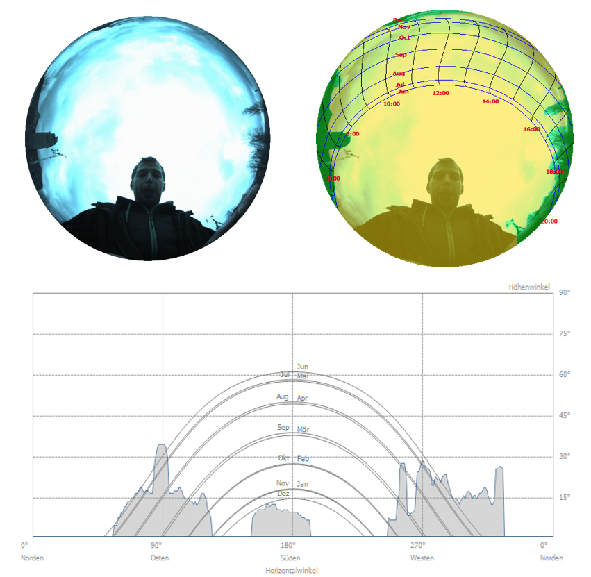
Recording a horizon line with the SunEye®.
See also