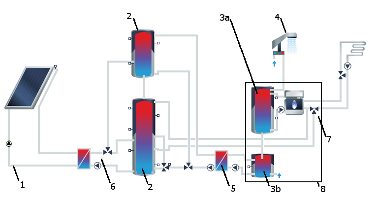
C7 - Two serial solar buffer tanks with DHW and space heating
The system consists of the following components:
| # | Hydraulic Configuration / Components | C7 |
|---|---|---|
| 1 | 1 or 2 collector loop(s) | x |
| 2 | 2 Solar buffer tank | x |
| The solar buffer tank is loaded by the solar system, exclusively. They are configured serially. The solar loop charges the upper solar buffer tank until the temperatures in the solar loop and in this tank are the same, then the lower solar buffer tank will be charged. If the temperature in the solar loop increases, then the upper solar buffer tank will be charged again. | ||
| 3a | DHW standby tank | x |
| The DHW standby tank is heated auxiliarily by the boiler. This provides more constant temperatures in the boiler buffer tank, ensuring an easier and safer operation of the boiler and the DHW as well. Both DHW standby tanks contain drinking water. | ||
| 3b | Solar standby tank | x |
| 4 | DHW | x |
| 5 | Buffer tank discharging station, charges the solar standby tank (3b) | x |
| The solar buffer tank (2) is discharged via a heat exchanger in order to preheat the DHW. | ||
| 6 | External heat exchanger at solar buffer tank | |
| The valve supports 2 different temperature levels at the solar buffer tank. The solar loop heats the solar buffer tank via an external heat exchanger. The solar flow can be switched between the solar buffer tank and the boiler buffer tank (valve). | ||
| 7 | Auxiliary heating with return flow boost | x |
| The auxiliary heating works via a return flow boost: The return of the DHW is stratified into the DHW standby tanks or the upper solar buffer tank, depending on the tank temperature. If the return temperature of the DHW is too high for discharging the standby tank, the return is switched to the upper solar buffer tank directly via a bypass. | ||
| 8 | DHW supply | x |
| The DHW supply includes a DHW standby tank (3a) and a solar standby tank (3b). Both DHW standby tanks contain drinking water. On the page “System Definition” > “Control” you can define an “Anti-Legionair’s” switch for short-term heating of the tank group. |
