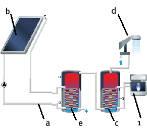
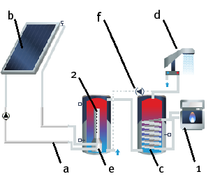
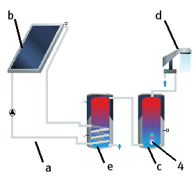
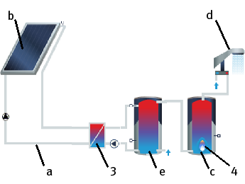
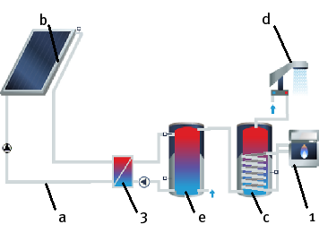
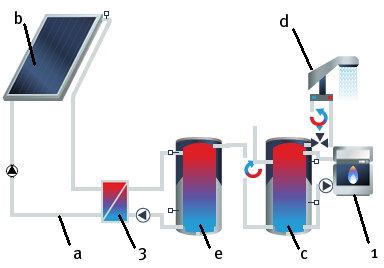
This is a system with 2 tanks or tank groups. The first serves as a solar tank; the second, downstream, as a standby tank. This configuration is ideal if several tanks are planned for the system on account of its size or an existing standby tank is to continue being used.
A2 - Hot Water System with 2 Tanks, without Layer Charging Device
A2.1 - Hot Water System with 2 Tanks, with Layer Charging Device
A2.2 - Hot Water System with 2 Tanks, the hot water tank is directly fired (US system)
A2.3 - Hot Water System with 2 Tanks, the solar tank has an external heat exchanger, and the hot water tank is directly fired (US system)
A2.4 - Hot Water System with 2 Tanks, the solar tank has an external heat exchanger, and the hot water tank is heated by the boiler.
A2.5 - Hot Water System with 2 Tanks, external heat exchanger for the solar circuit and boiler heat exchanger
The system consists of the following components:
| # | Hydraulic Connection / Components | A2 | A2.1 | A2.2 | A2.3 | A2.4 | A2.5 |
|---|---|---|---|---|---|---|---|
| 1 | External Boiler | x | x | x | x* | ||
| 2 | Stratification | ||||||
| x | |||||||
| 3 | External Heat Exchanger | x | x | x | |||
| 4 | Direct Firing in HW Tank | x | x |
- a: Collector Loop - x for all system types
- b: Collector Array - x for all system types
- c: Dual coil DHW tank - x for all system types
- d: DHW Consumption - x for all system types
- e: Single Coil Solar Tank (Monovalent) - x for all system types
- f: Destratification- x for all system types
*The internal heat exchanger in the boiler is not depicted.
On the System Definition > Control page, Control, an anti-Legionnaire’s switch can be used to briefly heat the tank group. A fixed time period on one or more days of the week is defined for this.
