Variant menu: System Definition > Storage tank or system layout
The solar buffer tank (P) is used in the A 17, B17, A18, B18, A14.1, P3, P5, Buderus SAT-VWS, Buderus SAT ZWE, and Vaillant Allstor systems and is bivalent. It includes, if needed, the tab Auxiliary heating.
The solar buffer tank (S) is used in the C6 system and is monovalent.
‘Parameters’ Page
Enter the manufacturer, type, and geometry of the tank and its insulation or select a tank.
Tank loading page
The controller and connection of the collector loop to the buffer tank is described on the Tank Loading page.
Sensor mounting heights: Enter the sensor mounting heights for the various tank sensors used to control the collector loop pumps. Enter the maximum tank temperature. If the tank is hotter than this temperature, the collector loop pumps are deactivated.
Heat exchanger: connection to the collector loop: Define the pipe connection heights and thermal loss of the tank connections for the loading circuit (flow and return). If the tank has a heating lance, its height is defined here. For the kA value, see the glossary.
Heat dissipation page
On this page, define the controller and connection of the heating support to the buffer tank.
Buffer bypass for return boost: In systems with heating support from the increasing of the heating return temperature, the mounting height of the sensors and the temperature difference (buffer bypass delta T) are defined here, which serve to activate the return boost to control the switching valves.
Bleed-off connections: If the heating loop is completely supplied from the tank, as with system type B18 for example, the pipe connection heights from the heat flow and return can be defined. Otherwise, only the return height. In addition, the return can be placed at 2 different heights in the tank. The corresponding valve switch is controlled using a sensor and temperature difference. Here, a tank bypass can also be defined, complete with a corresponding control sensor. This switch can be used to avoid warming a cold tank with the return and thereby increasing the system loss.
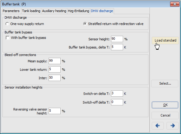
DHW Discharge page
Proceed as follows:
-
Enter the pipe connection heights from the flow and return and their loss. Additionally, define a tank bypass with a corresponding control sensor at this stage. This setup prevents a cold tank from being warmed up by the return, thereby reducing system losses.
-
The solar buffer tank is exclusively loaded by the solar system. If the temperature in the storage tank is sufficiently high, the heating return is raised by discharging the tank.
-
The return from the DHW station is layered at two different heights through a 3-way reversing valve and controlled based on the storage temperature in the solar buffer tank. If the return boost temperature is too high to discharge the buffer tank, a bypass switch is used to circumvent the solar buffer tank, directing the return from the DHW station directly into the boiler buffer tank.
Also see: C6 - Large-scale system for DHW with solar and boiler buffer tank, as well as heating controller
