Variant menu: Anlagendefinition
 System Definition > Collector Array > Collector > Parameters
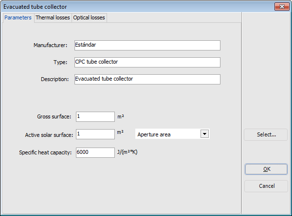
Entering the collector areas and specific heat capacity
The gross surface area is calculated from the external dimensions of the collector; however, the specific collector characteristic values typically do not relate to the gross surface area but an active solar surface taken from the reports by testing institutes.
Depending on the test institute, the active solar surface in flat-plate collectors is the absorber area or the aperture area. In evacuated tube collectors (e.g. with mirror constructions with vertical absorber), the active solar surface is frequently unrelated to real-world practice and is a purely theoretical value.
Collector – Thermal Losses
Variant menu: Anlagendefinition
 System Definitions > Flat-Plate / Tube Collector > Losses / Thermal Losses
Calculation of thermal and optical collector losses
The energy absorbed by the collector and output to the collector loop less heating losses is calculated as follows:
- Gdir: Part of solar irradiation striking a tilted surface
- Gdiff: Diffuse solar irradiation striking a tilted surface
- TCm: Average temperature in the collector
- TA: Air temperature
- fIAM: Incident angle modifier
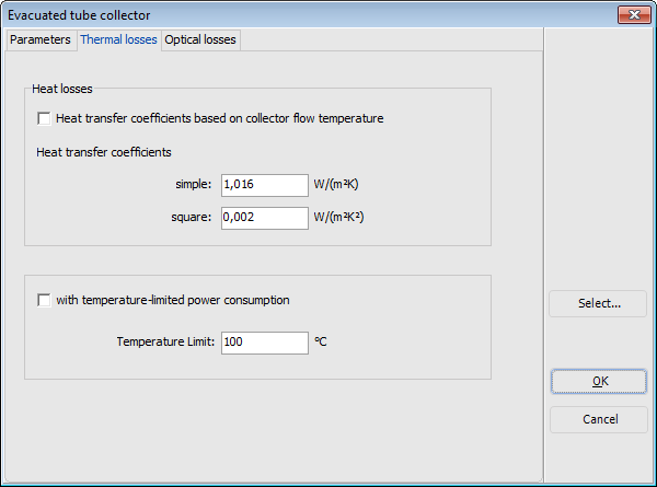
After deduction of optical losses (conversion factor and incident angle modifiers), a part of the absorbed radiation is lost through heat transfer and radiation to the environment. These losses are described by the heat transfer coefficient.
The heat transfer coefficient k states how much heat the collector releases into the environment per square meter of active solar surface and temperature difference between the average collector temperature and the environment in degrees Kelvin.
It is split into 2 parts, the simple and the quadratic part. The simple part ko (in W/m²/K) is multiplied by the simple temperature difference, the quadratic part kq (in W/m²/K²) by its square. This gives rise to the efficiency parabolae usually stated.
The specific heat capacity states the amount of heat per square meter of active solar surface that the collector, including its heat transfer medium content, can store at a temperature increase of 1 Kelvin. It is stated in Ws/m²K. This decides how quickly the collector reacts to the irradiation.
Collector – Optical Losses
Variant menu: Anlagendefinition
 System Definitions > Flat-Plate / Tube Collector > Losses / Optical Losses
Calculation of optical collector losses of a tube collector
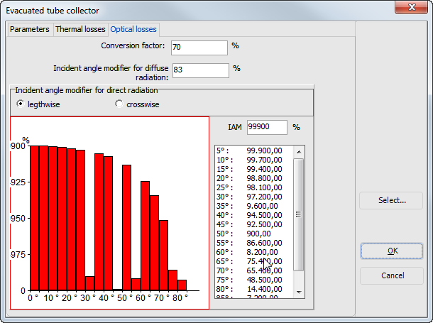
The conversion and incident angle modifiers determine the optical losses, i.e. how much of the irradiated energy is lost through reflection on glass and the absorber. The remainder is absorbed by the collector.
The conversion factor (in %) states amount absorbed with irradiation vertically to the collector surface area.
Incident angle modifiers describe the additional reflection losses when the sun is not positioned vertically above the collector surface area.
A constant diffuse incident angle modifier is stated for diffuse irradiation. For the direct fraction of radiation, this is defined using the incident angle. In the process, flat-plate and evacuated tube collectors are treated differently.
For flat-plate collectors, the loss factors for all incident angles are calculated from the incident angle modifier for the incident angle at 50% deviation from the vertical.
For evacuated tube collectors, the reflection losses differ depending on whether the irradiation is reflected lengthwise or crosswise to the tube. Due to the multitude of different designs, these dependencies cannot be specified by one input value. The incident angle modifiers must be given lengthwise and crosswise to the tube at 5° intervals for all incident angles between 0 and 90°. When crosswise, these modifiers can have a value higher than 100% due to concentration on curved glass or as a result of mirror constructions.


