Variant menu: Anlagendefinition
 System Definition > Collector Loop > Collector Loop or system schematic
Dialog for connecting the collector loop
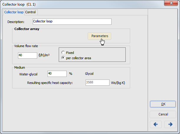
The Collector Array is defined via the Parameters button on the Collector Loop page.
The volumetric flow rate states how many liters of heat transfer medium are to flow through the collector in total per hour or per square meter. This volumetric flow rate crucially defines which temperature is transported in the flow of the collector loop. The calculation of the collector array pipe diameter is also dependent on this entry.
Water or a water/glycol mixture can be used as the heat transfer medium. The resulting specific heat capacity is then displayed.
Tank Connection / External Heat Exchanger
Variant menu: Anlagendefinition
 System Definition > Collector Loop > Tank Connection
Connection > Collector Loop > Tank Connection for systems with external heat exchanger, e.g., system A3.2
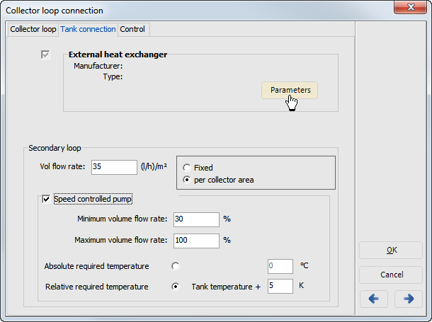
In systems with an external heat exchanger, the Collector Loop Connection features the additional Tank Connection page, on which the heat exchanger can be selected.
For the secondary loop, you can enter the volumetric flow rate as an absolute value or per m² of collector surface area.
The Speed Controlled Pump option in the secondary loop means that the volumetric flow rate of the pump is controlled in this way to reach the target temperature. You can set a fixed target temperature or enter one relative to the tank temperature.
DHW Tank / Space heating buffer tank
Variant menu: Anlagendefinition
 System Definition > Collector Loop > DHW Tank / Space heating buffer tank
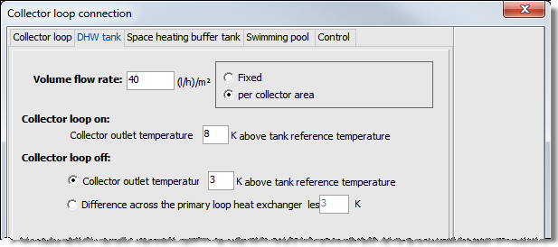
Connection > Collector Loop, connection of a dual coil DHW tank, e.g., system B3.1
You can enter the volumetric flow rate as an absolute value or per m² of collector surface area.
Define different conditions for switching on or off of the collector loop, relative to
- the collector outlet temperature,
- the tank reference temperature, and
- the temperature spread across the primary loop heat exchanger.
Control
Variant menu: Anlagendefinition
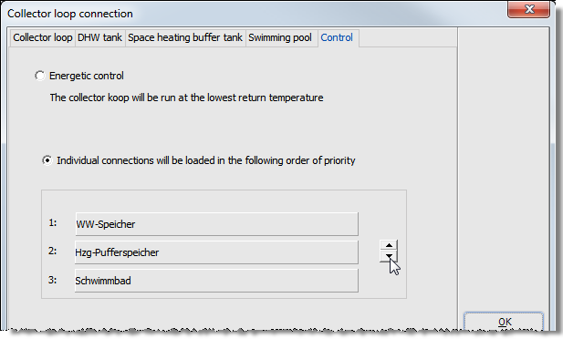
 System Definition > Collector Loop > Control
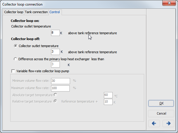
Input dialog for Collector loop connection > Control page
Example: system A6, A6.1, similar, but without heat exchanger: A5, A10,
Input dialog for connection to collector loop, Control page, more than one tank
Requisites: System B3, B3.1, Input dialog for connection to collector loop, Control page, more than one tank
