Variant Menu: Results > Project Report > Energy Balance
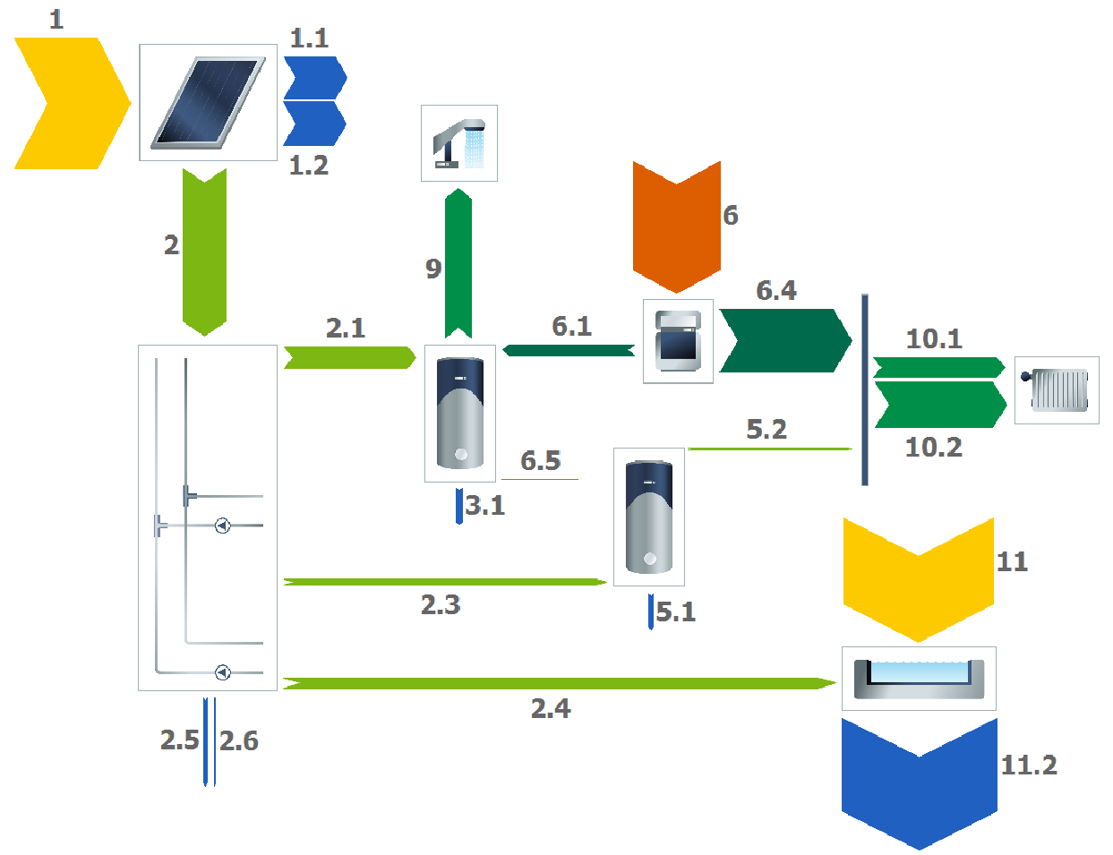
A detailed energy balance for a calculated variant is available in the project report, both in tabular form and graphically displayed like in a Sankey diagram.
The energy balance provides information on the energy flows TSOL uses as a basis for calculation and analysis. TSOL considers various calculatory areas corresponding with the borders in the system layout. Three calculatory areas are presented here in the energy balance: collector loop, system (beyond the collector loop), energy supply to end consumer (DHW heating and heating loop).
Legend:
The flow diagram shows the energetic flows:
- Yellow: Solar radiation on the collector reference surfaces.
- Blue: Losses from the collector circuit, storage, and piping.
- Red: Additional energy supplies (boiler or swimming pool radiation).
- Green: Portions that transfer as benefits from one balance area to another.
Table of Balance Parameters
| Typ | Direction of energy flow via gross module area |
|---|---|
| Energy balance collector loop: | |
| Fraction [%] (solar fraction) | The proportion of energy transmitted by the solar system to the standby tank to the total amount of energy transmitted to the standby tank (from the solar system and auxiliary heating). |
| Solar fraction related to consumption [%] | The proportion of energy transmitted by the solar system to the standby tank to the total amount of energy transmitted to the standby tank (from the solar system and auxiliary heating), in relation to consumption only. The calculation differs depending on the storage tank (dual coil or combination tank). |
| Efficiency [%] (system efficiency) | Ratio of energy generated by the solar system to the energy irradiated onto the active solar surface of the collector array. |
| Irradiation onto active solar surface area [kWh] | Energy radiating onto the tilted surface of the collector. Shading is taken into account. |
| Optical losses [kWh] | The conversion and incident angle modifiers determine the optical losses arising from reflection on glass and absorber. |
| Losses – external piping [kWh] | Heating losses at the pipes installed outside the thermal envelope. |
| Losses – internal piping [kWh] | Heating losses at the pipes installed inside the thermal envelope. |
| Thermal collector losses [kWh] | Heat losses from the collector to the environment. The heat transfer coefficient is split into a linear and quadratic part for calculation. |
| Energy output by the collector loop [kWh] | Energy at the gross module area, from the collector loop to the calculatory area of the system. |
| Energy transferred from the collector loop to the tank [kWh] | Energy at the gross module area, from the collector loop to the tank. |
| Energy transferred from the collector loop to the heating [kWh] | Energy at the gross module area, from the collector loop to the heating. |
| Energy transferred from the collector loop to the swimming pool [kWh] | Energy at the gross module area, from the collector loop to the swimming pool. |
Energy balance system:
| Energy output by the collector loop [kWh] | Energy at the gross module area, from the collector loop to the calculatory area of the system. | | Energy output by the boiler [kWh] | Energy at the gross module area, from the auxiliary heating to the calculatory area of the system. | | Storage losses [kWh] | Heat losses from the storage tank to the environment (ambient temperature at boiler). | | Total losses [kWh] | Heat losses of the swimming pool |
Overview energy balance system:
| Balance error [kWh] | Absolute balance error due to numerical diffusion. | | Balance error [%] | Relative balance error | | Supplied [kWh] | Energy flowing into the system (+) | | Removed [kWh] | Energy flowing from the system to the end consumer (->) | | Losses [kWh] | System energy losses (-) | | Change of energy level [kWh] | Change of energy within the tank (and swimming pool), relative to period under consideration. | | Energy supply DHW heating [kWh] | Energy at the gross module area for DHW heating. (before mixing valve) | | High-temperature space heating loop energy [kWh] | Heat transfer from the gross module area to high-temperature space heating loop. | | Low-temperature space-heating loop energy [kWh] | Energy from gross module area to the low-temperature space heating loop. |
