Tracking
alpha_M und gamma_M in Quaschnings Grafik umbenennen
Depending on the type of tracking, the alignment and inclination angles of the PV modules change during the simulation process. For each time step, the angle of incidence of the sun’s rays is then calculated from the inclination and orientation angles of the PV modules and the position of the sun.
Tracking types
| Tracking type | $\alpha_\text{E}$ | $\gamma_\text{E}$ | Description |
|---|---|---|---|
None 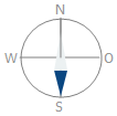 |
steady | steady | With permanently mounted modules, inclination and alignment remain constant. |
1-axial North-South  |
variable | variable | The PV modules are oriented to the equator, while the axis of rotation is on the north-south plane. This means that both inclination angle and alignment angle change during the simulation. |
1-axial East-West  |
steady | steady | The PV modules are mounted so that they can rotate around the east-west axis. Here the angle of inclination changes, but not the alignment angle of the modules. |
1-axis vertical rotation axis 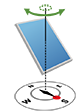 |
variable | steady | The PV modules are elevated with a fixed angle of inclination and track the solar azimuth by rotating the vertical axis. This means that the angle of inclination remains constant while the alignment angle changes. |
2-axis 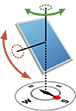 |
variable | variable | The PV modules follow the inclination and orientation of the sun – both angles change in the course of the simulation |
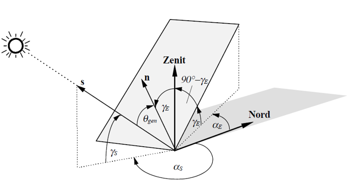
Angle of incidence
The angle of incidence of the radiation on the PV modules $\theta_\text{gen}$ can be calculated from the geometric events.
- $\alpha_\text{S}$: Orientation of the sun
- $\gamma_\text{S}$: Elevation of the Sun
- $\alpha_\text{M}$: Orientation of the module
- $\gamma_\text{M}$: Elevation of the module
$\cos \theta_\text{gen} = - \cos \gamma_S \cdot \sin \gamma_M \cdot \cos (\alpha_S - \alpha_M + \pi) + \sin \gamma_S \cdot \cos \gamma_M$
Horizon line with sun position A.
Source of graphic: Quaschning: “Simulation der Abschattungsverluste bei solarelektrischen Systemen” pdf