Cables
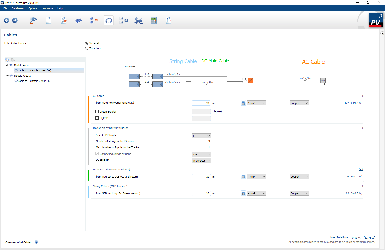
Overview of the Cables navigation page (detailed cable losses)
The cable losses of the planned PV system are defined on the ![]() cable navigation page. When entering the cable losses you can choose between:
cable navigation page. When entering the cable losses you can choose between:
If the detailed cable losses are selected, the losses can be calculated by specifying the cable lengths, cable cross-sections and cable materials. The generator output under standard test conditions is used as a design aid or as a reference specification. With the data given there, the cable losses in the simulation are calculated for each time step. In addition, it is possible to dimension electrical protective devices and define the DC topology via different distributors. If total loss is selected for the input of cable losses, the cable loss value specified there is used across-the-board in the simulation.
Cable losses: Total
A general cable loss can be entered here. The total cable loss can also be calculated using the 3D cable plan. The amount of calculated cable loss from the 3D environment is then displayed below the total loss.
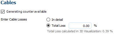
Visualization losses from 3D environment
Cable losses: Detailed
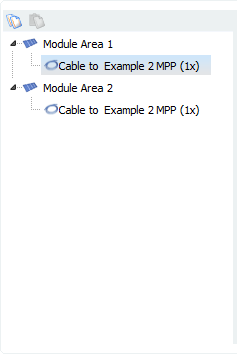
The selection of the cable harnesses is made via the tree view. The wiring harnesses are sorted by module area, and show all connections per module area. To determine the cable losses, the following procedure is essentially necessary:
Select wiring from tree view
Specify DC topology
Define cables
- Length
- Diameter
- Material
(optional) Define protective devices
The respective wiring can be selected from the tree view. There all connections per module area are listed. Using the  button, the cable properties (length, material, cross-section) of a circuit can be copied and pasted into other circuits with
  .
.
In the  DC topology, the MPP tracker to be configured and the position of the DC circuit breaker are selected. If more than one string is present, you can select how the strings are to be combined (e.g. using the generator connection box (GAK) or T-connector).
In order to calculate the respective cable losses, the length, the cross-section and the material must be specified for each cable type. Altogether there are three different cable types in PV*SOL®:
 AC cables
 DC main line (only active if more than 1 line is connected)
 String line
Once the corresponding data per cable have been entered, the cable losses per cable and the maximum total losses can be read. On the one hand the relative cable losses are calculated and on the other hand the absolute losses in watts. The reference value of the relative losses is the connected generator power. If, for example, a circuit consists of 2 identical strings, the entire generator power (minus the string losses) is applied to the DC main line and half the generator power is applied to each string.

Description of a cable type
With the button  cable cross-sections for cable losses <1 % can be calculated automatically.
Various optional protective devices can be added on the AC side. By selecting the checkboxes, you can determine whether a circuit breaker and a FI/RCD should be installed.

Checkboxes AC protective devices
PV*SOL® calculates the necessary protection classes, such as the characteristics of the circuit breaker. For inverters with transformers, the characteristics of the miniature circuit breaker K and without transformer B. The reference current for the design of the protective devices is 1.1 times the maximum output current of the inverter.
See also