Plans
Overview of the page Plans
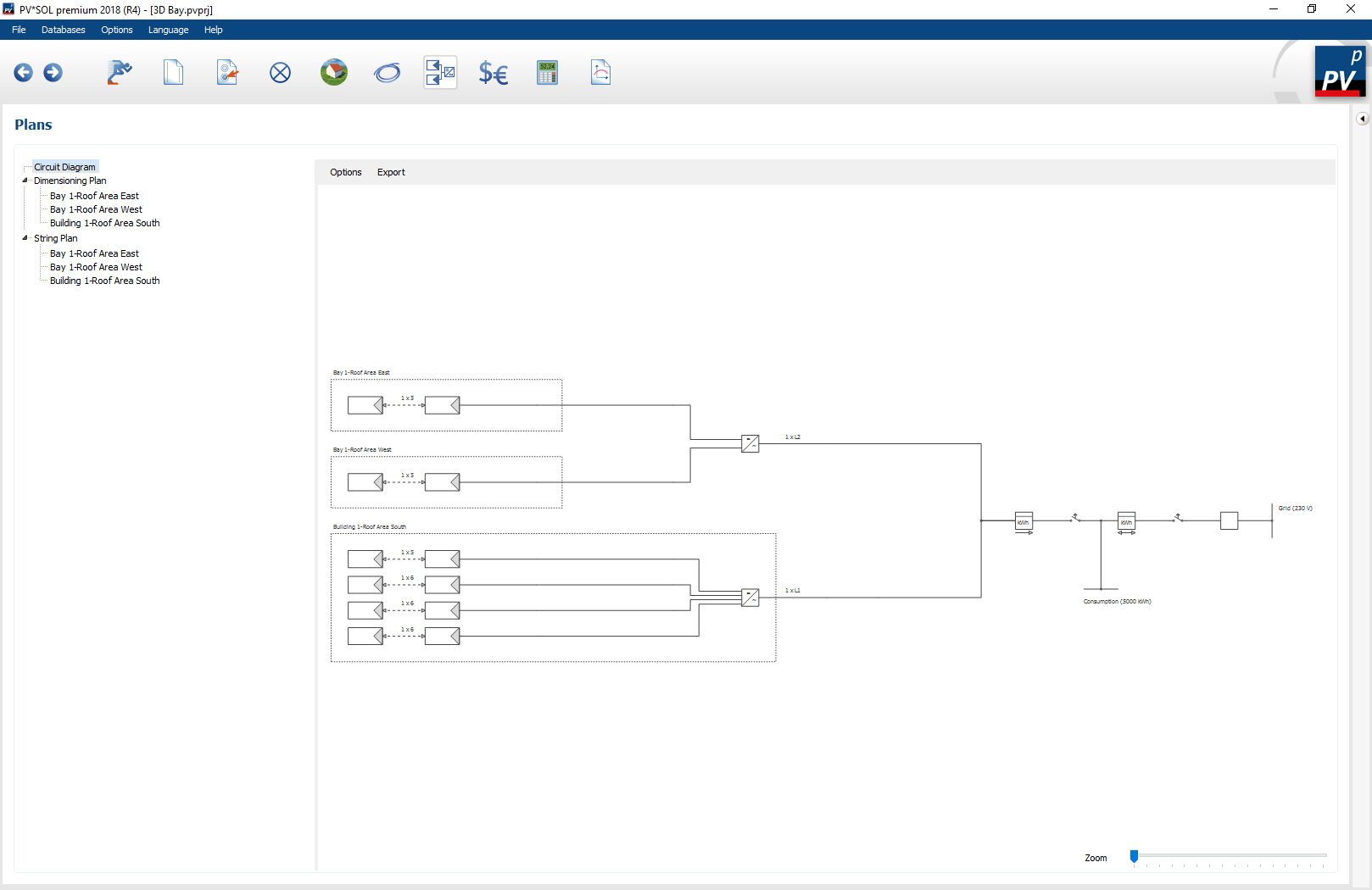
All technical drawings and plans are displayed on the ![]() plans page. PV*SOL® includes the following plans:
plans page. PV*SOL® includes the following plans:
- Schematic circuit diagram
- Dimension plan (only for
 3D design )
 - String diagram (only for 3D design)
The plans can be adapted via the menu item and exported to different formats via . The formats DXF, Bitmap and PDF are available for export.
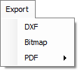
The DXF format (Drawing Interchange Format) is specified by Autodesk and is under continuous development. Further information and a free DXF viewer are available at http://www.autodesk.com. The DXF is exported in AutoCAD Release 11$/$12. A processing of DXF is provided in most CAD programs of other manufacturers.
Schematic circuit diagram
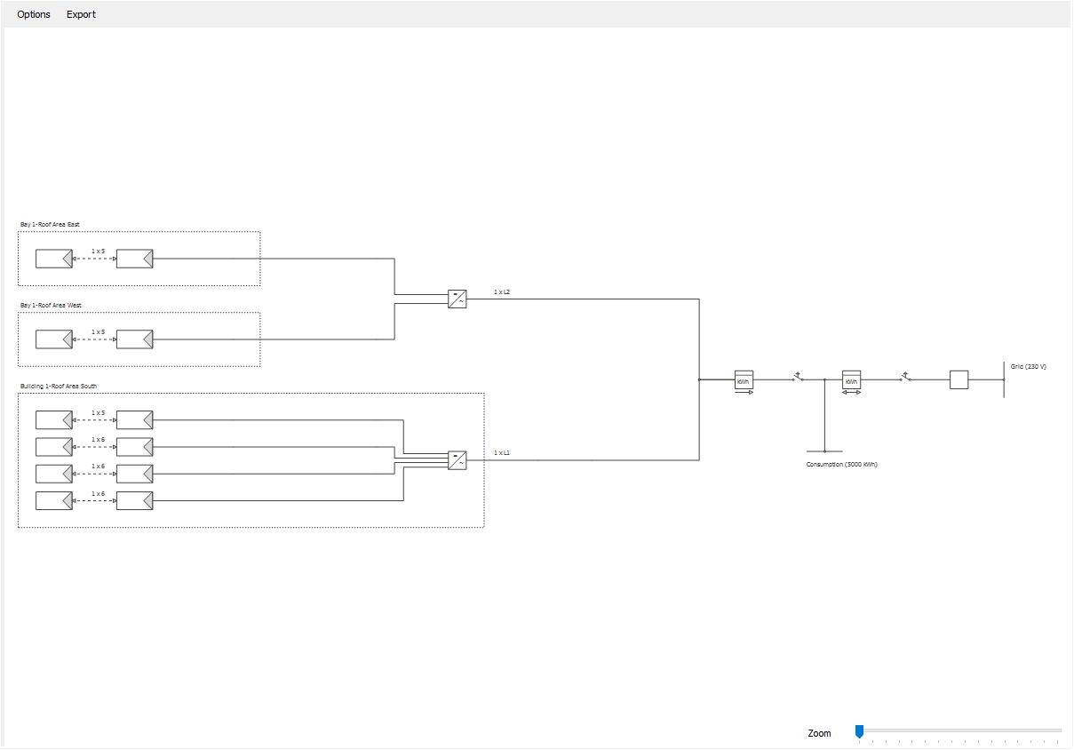
The circuit diagram is a representation of your PV system with standardized circuit symbols. The following options can be set in the menu item:
- Key
Displaying the circuit symbols and more detailed product information - Drawing frame
A drawing frame according to DIN EN 62446 is mounted around the circuit diagram. Some contents are already filled from the project data.
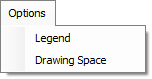
Dimension plan
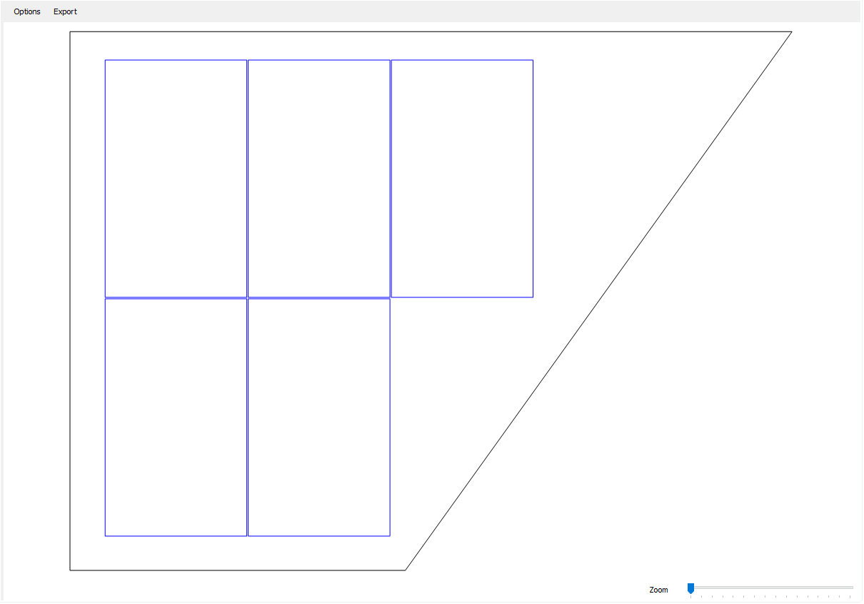
When closing the 3D visualization, dimension plans are automatically generated for all occupancy areas on which PV modules are located. Here it is sufficient if an allocation surface was interconnected. The floor plans of the occupancy objects and lock objects are displayed in black and the PV modules in blue on the dimension plan. For the elevated systems, the module rows are also displayed. The following dimensions are also displayed in the plan:
Roof-parallel system:
- Dimensions of roof edges
- Distance of the first module formation to the left and lower roof edge
- The dimensions (width x length) of a module
- The horizontal and vertical module spacings
Mounted system:
- Row spacing
- Alignment to the occupancy area using the example of a module row
The following options can be set in the menu item :
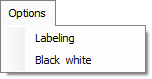
- Dimensions
Showing and hiding dimensions - Black/White
Displaying the dimension plan in black and white only
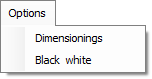
String diagram
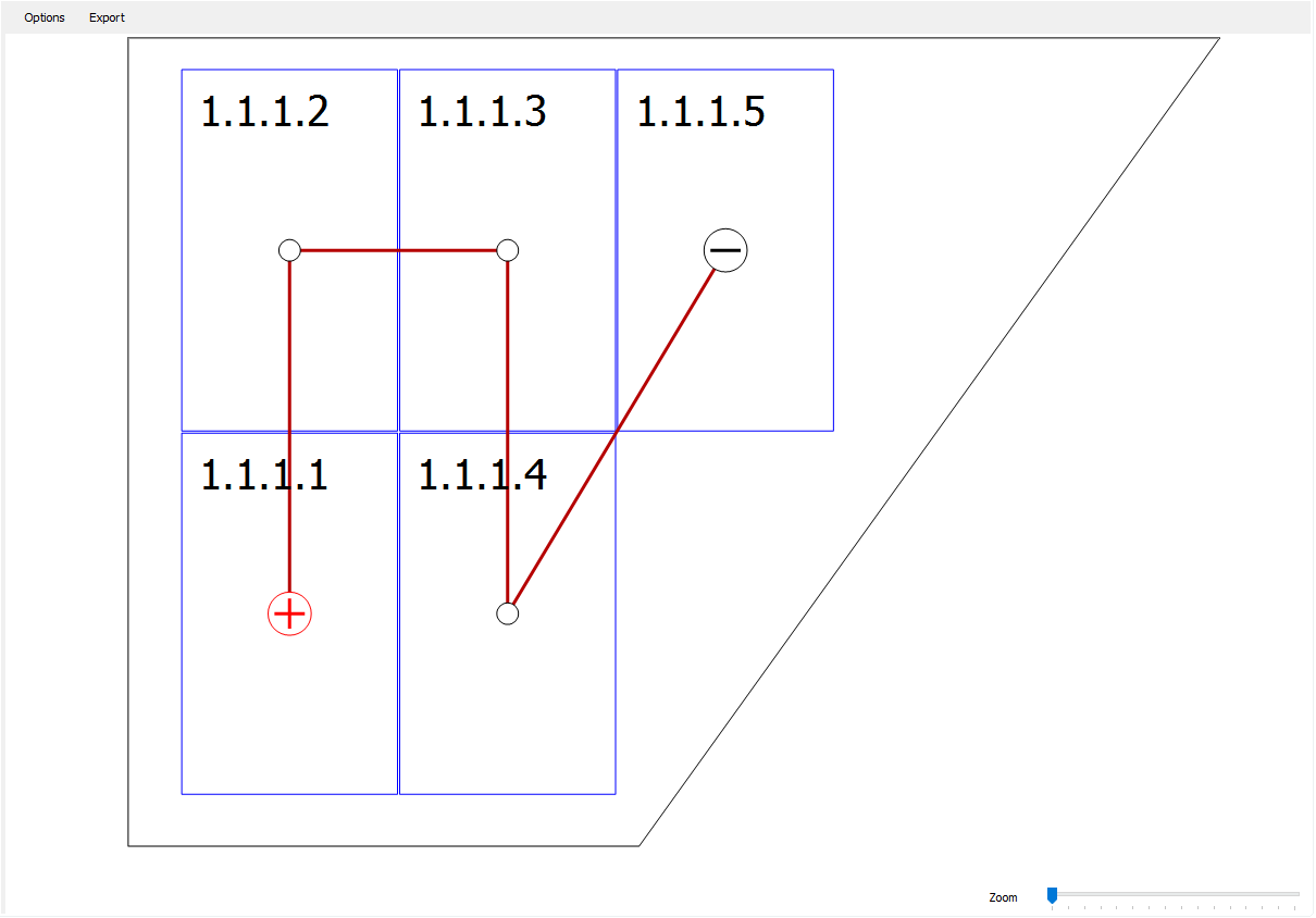
When the 3D visualization is closed, string plans are automatically generated for all occupancy areas on which connected PV modules are located. The floor plans of the occupancy objects and lock objects are displayed in black and the PV modules in blue on the string diagram. For the elevated systems, the module rows are also displayed.
The following options can be set in the menu item :
- Caption
Show and hide module labels - Black/White
Display of the string plan exclusively in black and white