General
Cluster
Page: System setup - Cluster
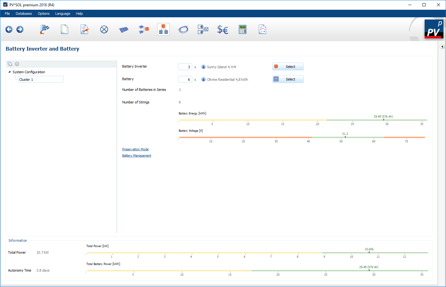
The individual system configurations (clusters) are displayed in the tree view. A cluster consists of one or more battery inverters and batteries of the same type.
- In three-phase systems, you can duplicate Cluster by clicking on the
 button or delete them via
  .
. - Only one cluster is permitted for single-phase systems.
To estimate the selected cluster, two control bars for battery energy and battery voltage are also displayed.
| Parameters | Description |
|---|---|
| Battery energy | 2 kWh battery energy is required per kW battery inverter power. |
| Battery voltage | The permissible DC voltage range of the battery inverter is displayed. The voltage of the battery pack must correspond to the nominal DC voltage of the battery inverter. |
Battery-conserving operation
Cluster: Battery-conserving operation
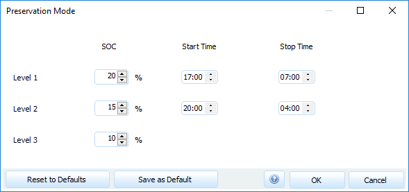
In the menu item Battery-saving operation, start and stop times are selected depending on the battery charge status (SOC). The battery-saving operation is intended to ensure that a deep discharge of the battery is prevented as far as possible in the selected period when the energy supply is low, thus avoiding a total failure of the system and damage to the battery. Outside the times of battery-saving operation, the inverter runs in normal operation. A total of three stages are defined for battery-saving operation.
Level 1: Transition area, e.g. for late afternoon and morning. If the specified state of charge (SOC) is reached within the defined period, the battery inverter switches to the standby state. In the next simulation time step it is checked whether energy is available for charging the batteries (PV system or additional generator). If so, the battery inverter exits battery-conserving operation. If not, protection mode level 1 remains active.
Level 2: Area for low energy times (at night). If the specified state of charge (SOC) is reached within the defined period, the battery inverter switches to the standby state. The inverter is then started every two hours and attempts to charge the battery from the AC side (PV system or auxiliary generator). If this does not succeed, the battery inverter remains in battery-conserving operation level 2.
Level 3: Protects against deep discharge and the associated damage to the battery. In this case, the battery inverter is completely switched off and the simulation is terminated. A corresponding message appears.
Charging strategy
Cluster: Charging strategy
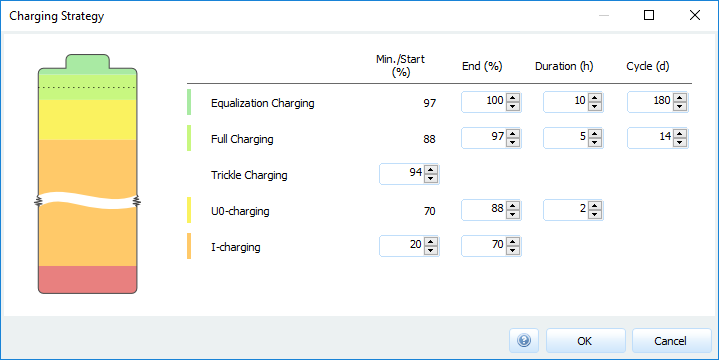
Here you can adjust the strategy for charging the batteries. The different charging controls are defined depending on the state of charge (min/start, end), charging time and cycle frequency.
System information
System information
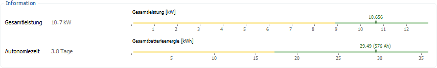
The information area shows all important information of the entire system (all clusters used). The bars visualize how the selected battery system is designed.
| Parameter | Description |
|---|---|
| Overall performance | The total installed battery inverter power is displayed in relation to the peak consumption. Here, the power of the battery inverter for 60 minutes is used, which is also used for the automatic design. |
| Total battery energy | At least 4.8 kWh battery energy is required per kWp PV generator output. |
| Autonomy time | Shows the actual autonomy time based on the mean value of the electrical loads. |
See also