Plans
Overview of the page Plans
All technical drawings and plans are displayed on the ![]() plans page. PV*SOL® can create the following plans:
plans page. PV*SOL® can create the following plans:
- Schematic circuit diagram
- Dimension plan (only for
 3D design )
 - String diagram (only for 3D design)
The plans can be adapted via the menu item and exported to different formats via . Different export formats are available for the export depending on the plan.
Plan-dependent overview of export formats
| Plan | Export formats |
|---|---|
| Schematic circuit diagram | PDF, PNG, SVG |
| Dimensioning plan | PDF, PNG, DXF |
| String diagram | PDF, PNG, DXF |
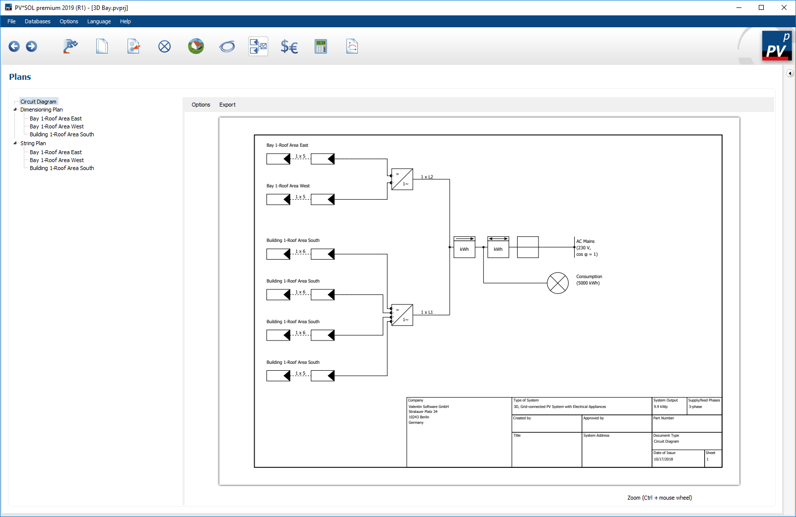
Schematic circuit diagram
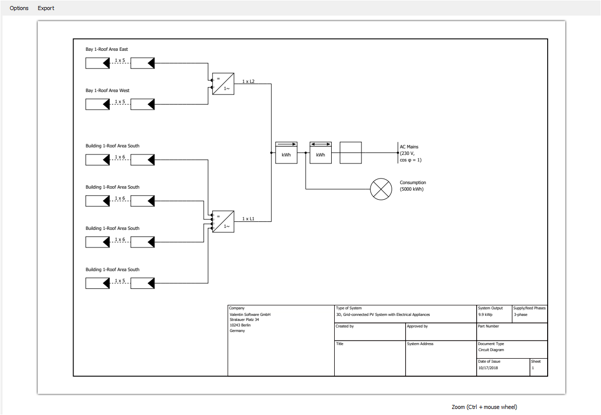
Detail view circuit diagram
The circuit diagram is a representation of your PV system with standardized circuit symbols. The following options can be set in the menu item :
- Legend
Display of the circuit symbols used and more detailed product information. The legend can be anchored at different positions in the plan. - Drawing frame
A drawing frame according to EN ISO 5457 is spanned around the circuit diagram and a title block according to EN ISO 7200 is created. The title block is filled with the project data. - Plan Properties
In the Plan Properties dialog the page format and the alignment of the schematic can be adjusted.. In addition, the scaling and color of the schematic can be changed.- Scaling options
- Adapt to page format
The display size of the schematic is adapted to the available drawing area. - None
The display size of the schematic remains unchanged. If the size of the circuit diagram exceeds the drawing area, the diagram is reduced in size.
- Adapt to page format
- Colour options
- Background coloured
- Cables coloured
- None (black and white)
- Background coloured
- Scaling options
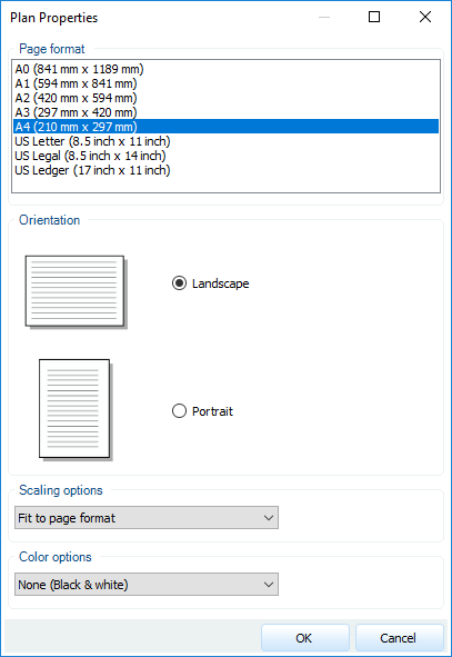
Dialogue plan properties
Dimension plan
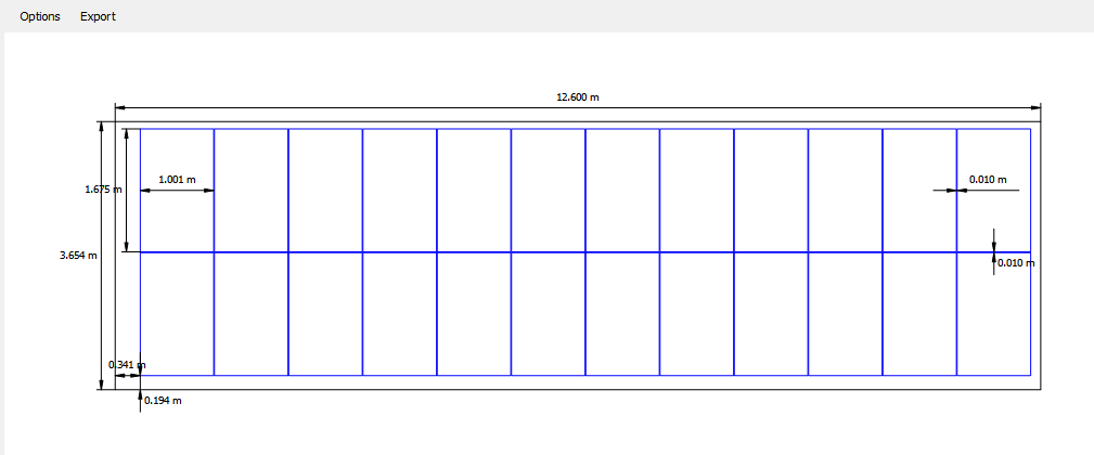
Detail view dimensioning plan
When closing the 3D visualization, dimension plans are automatically generated for all occupancy areas on which PV modules are located. Here it is sufficient if an allocation surface was interconnected. The floor plans of the occupancy objects and lock objects are displayed in black and the PV modules in blue on the dimension plan. For the elevated systems, the module rows are also displayed. The following dimensions are also displayed in the plan:
Roof-parallel system:
- Dimensions of roof edges
- Distance of the first module formation to the left and lower roof edge
- The dimensions (width x length) of a module
- The horizontal and vertical module spacings
Mounted system:
- Row spacing
- Alignment to the occupancy area using the example of a module row
The following options can be set in the menu item :
- Dimensions
Showing and hiding dimensions - Black/White
Black and white display of the dimensioning plan
String diagram
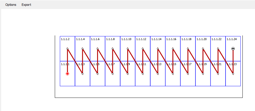
Detail view string diagram
When the 3D visualization is closed, string plans are automatically generated for all occupancy areas on which connected PV modules are located. The floor plans of the occupancy objects and lock objects are displayed in black and the PV modules in blue on the string diagram. For the elevated systems, the module rows are also displayed.
The following options can be set in the menu item :
- Caption
Show and hide module labels - Black/White
Black and white display of the string plan