Cables
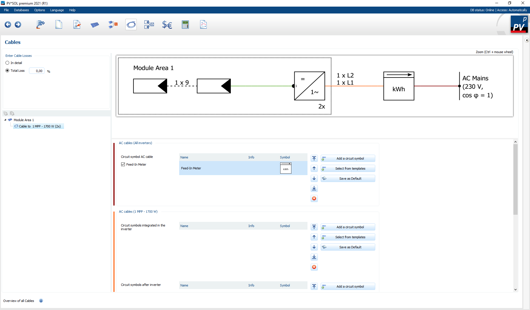
Overview of the Cables navigation page (detailed cable losses)
The cable losses of the planned PV system are defined on the
![]() Cables navigation page. When entering the cable losses you can choose between:
Cables navigation page. When entering the cable losses you can choose between:
The safety devices can be defined independently of the cable losses. If Total loss is selected for the input of the cable losses, the cable loss value specified there is used in the simulation as a lump sum. If the detailled cable losses are selected, the losses are calculated by specifying the cable lengths, cross-sections and materials. The generator power under STC conditions is used as a design aid or orientation parameter. With the data given there, the cable losses in the simulation are calculated for each time step. In addition, it is possible to dimension electrical protective devices and define the DC topology via different distributors.
The
 button can be used to copy the cable properties (length, material, cross section) and the safety devices of a circuit and paste them into other circuits using
 .
.
Cable losses: Total
A general cable loss can be entered here. The total cable loss can also be calculated using the 3D cable plan. The amount of calculated cable loss from the 3D environment is then displayed below the total loss.
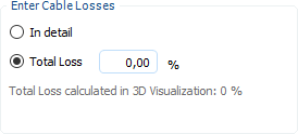
Visualization losses from 3D environment
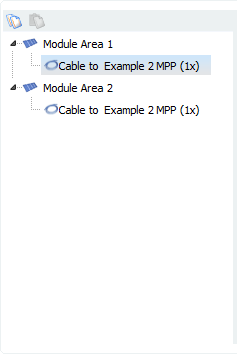
Cable losses: Detailed
The selection of the cable harnesses is made via the tree view. The wiring harnesses are sorted by module area, and show all connections per module area. To determine the cable losses, the following procedure is essentially necessary:
-
Select wiring from tree view
-
Specify DC topology
-
Define cables
- Length
- Diameter
- Material
-
(optional) Define safety devices
The respective wiring can be selected in the tree view. All connections of the respective module surface are listed there.
With the
 DC topology, the MPP tracker to be configured and the position of the DC disconnector are selected. The selection of the DC disconnector depends on the number of connected strings and the number of DC inputs of the inverter used.
Selection of possible DC disconnectors
| Condition | DC disconnector |
|---|---|
| Number of strings <= Number of DC inputs Inverter | None |
| Number of strings = 2 | T-plug (with and without integrated overvoltage protection) |
| Number of strings > 1 | Generator connection box (with and without integrated overvoltage protection) |
In order to be able to calculate the respective cable losses, the length, cross-section and material must be specified for each cable type. In PV*SOL® losses can be defined for the following cable types:
-
 AC cables
 -
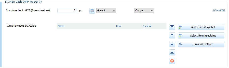
 DC main line (only active if a DC disconnector has been selected)
 -
 String line
If the corresponding specifications are selected, the cable losses per cable and the maximum total losses can be read off. On the one hand the relative cable losses are calculated, on the other hand the absolute losses in Watt. The reference value for the relative losses is the connected generator power. If, for example, a circuit consists of two identical strings, the entire generator power is applied to the DC main line (minus the string losses) and half the generator power is applied to each string.
Overview DC cables
Via the button
 cable cross sections for cable losses <1 % can be calculated automagically.
Safety devices
In PV*SOL® different safety devices can be defined for each type of cable. The following cable types are available:
-
 AC-cables (All inverters)
 -
AC-cables (Selected inverter)
-
DC main line (only active if a DC disconnector has been selected)
-
String line
Depending on the type of system, it is possible to activate or deactivate a feed-in counter, a bidirectional counter and the house connection in the
AC-cable (all inverters). The facilities are activated by default.
The
 button can be used to add appropriate devices when selecting the safety devices. In the dialog that appears, different safety devices are available for selection depending on the installation location. Each device can be provided with additional information which then appears in the circuit diagram. (see Pages > Plans).
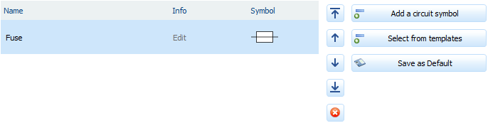
Selection of safety devices
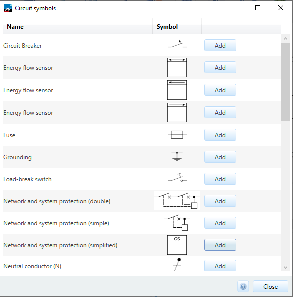
Dialogue safety devices
Templates

Dialog templates
In PV*SOL®, a wide variety of circuit symbols can be summarised and saved in templates. Once created, the templates can be reused in any PV*SOL® project. Templates that have already been created can also be changed and deleted at any time.
The dialogue for selecting and managing the templates can be opened via the
 button.
In each template, the switching characters used can be arranged as required. It is also possible to add additional information (info field) to the switch symbols in the templates. However, as the selectable symbols differ depending on the installation location, each template must be assigned an installation location. For example, if you want to select circuit symbols from a template for the “AC cable circuit symbol” area, a template with the installation location “AC cable” must be selected. If the installation location of a template is changed, all invalid circuit symbols are automatically deleted.

Edit templates dialogue
See also