PV Modules
Page PV-Modules
On the navigation page
![]() PV-Modules all photovoltaic modules to be simulated are defined and combined to module surfaces.
Each module surface contains a module type with an individual orientation.
PV-Modules all photovoltaic modules to be simulated are defined and combined to module surfaces.
Each module surface contains a module type with an individual orientation.
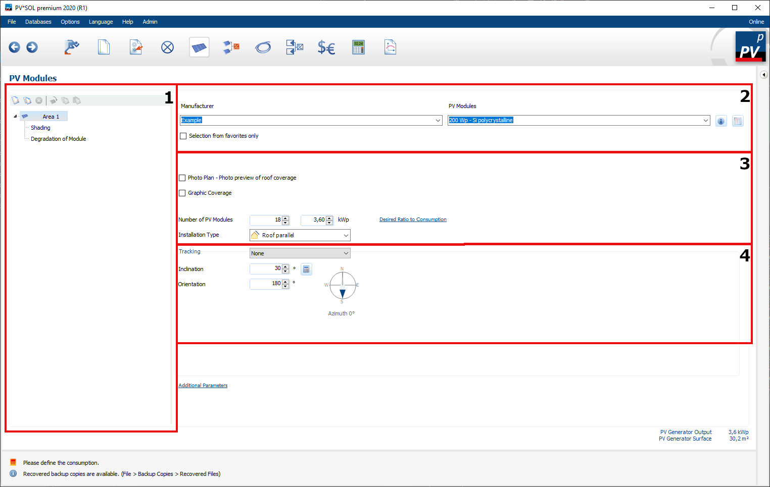
In the tree view in area 1 the different module areas are created and managed. Shading and Module Degradation can be edited for each module area. In area 2, the respective PV module is selected from the Database. In area 3 the number of modules and the installation situation are defined. The number of PV modules can be set
- using Photo Plan
- using Graphic Coverage or
- manually
In area 4 the tracking and the alignment of the entire module area is defined. Five different module tracking types are predefined in PV*SOL®.
Defining a module area
-
Creating a new module area
The first module area is defined by default.
New module areas can be created via the selection bar (area 1) or via the context menu of an existing module area (right click).
With this button
(area 1) or via the context menu of an existing module area (right click).
With this button
 you can create new module areas or copy existing module areas via
 .
. -
(optional) Renaming a module area
-
Selection of the PV module to be used
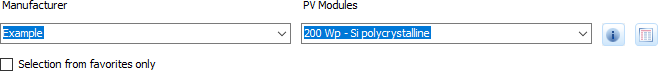
PV-Module selection
From the Manufacturer and PV Modules drop down menus, select a photovoltaic module you want to use for the current module area. Click the
 button for detailed information on the selected PV module.
Alternatively, click the
button for detailed information on the selected PV module.
Alternatively, click the
 button to access the database of PV modules.
The desired PV module can also be selected there.
button to access the database of PV modules.
The desired PV module can also be selected there.If the desired PV module does not exist in the database, you can create your own data records and use them.
-
Define the number of modules or module assignment
- Photo Plan
- Graphic Coverage
- Manually
-
Select Installation type
-
Define Tracking, including module orientation
-
(optional) Define Additional Parameters
Define optimum number of modules
Via Desired ratio to consumption the number of modules can be adjusted as a percentage to an annual consumption. Depending on the module inclination, the orientation and the tracking system, the number of modules is calculated in order to generate the corresponding PV energy.
If no consumers are defined, a fictitious annual consumption can be selected as calculation basis in the dialogue “Ratio of PV energy (DC) to consumption”.
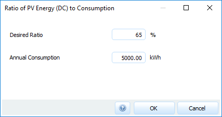
Dialogue: Ratio of PV energy (DC) to consumption, without consumer
In the case of PV systems with defined consumers, the desired ratio can also be extended to a self-selected observation period. In addition to annual consumption as the reference period, you can choose individual months and the worst month of the year.
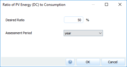
Dialogue: Ratio of PV energy (DC) to consumption, with consumer
Installation type
| Installation type | Description |
|---|---|
| Roof parallel | The PV modules are mounted at a distance above the roof cladding. |
| Roof-integrated - rear ventilation | The PV modules are mounted on a substructure parallel to the roof cladding. The rear ventilation contributes to the cooling of the modules. |
| Roof-integrated - no rear ventilation | The PV modules form the roof cladding. |
| Mounted - Roof | The PV modules are elevated mounted on a roof. |
| Mounted - Open Space | The elevated PV modules are mounted at ground level. |
| Floating PV | The PV modules are mounted on a construction floating on water. |
Tracking
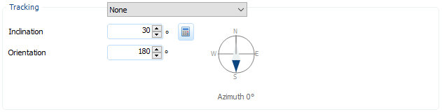
PV Modules: Tracking
Tracking types
| Tracking type | Description | Tracking scheme |
|---|---|---|
| None | No module tracking is desired. Only the inclination and orientation of the modules is determined. | 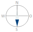
|
| Single North-South Axis | The PV modules are oriented to the south, while the axis of rotation is in the north-south plane. The inclination of the rotary axis is defined via Rotation Axis Incline. The opening angle can be defined via Rotation Angle of Opening. The Surface Usage Factor indicates the distance between the tracked module rows. A surface usage factor of 1 means that the distance from one module row to the next is equal to the width or height of the module. If the surface usage factor is 0, the next row of modules is infinitely far away. A surface usage factor of 0.5 means that the distance is two module lengths or widths. |
|
| Single East-West Axis | The PV modules are mounted so as to allow rotation around the east-west axis, which is restricted by Rotational Angle of Opening. | |
| Single Vertical Rotation Axis | The PV modules are elevated with a fixed angle of inclination and track the solar azimuth by rotating the vertical axis. The opening angle can be defined via Azimuth Angle of Opening. | |
| Biaxial | In this variant, the PV module can be rotated in two axes.The Maximum Inclination defines the greatest possible module inclination up to 90°, Azimuth Angle of Opening defines the opening angle. |
The specified opening angle applies in both directions. If you enter 20°, for example, the module can rotate 20° to both sides.
If no tracking is selected, the inclination of the module surface can be optimized with the button  (Optimizing the inclination angle).
With a given orientation, the system searches for the orientation with the highest irradiation on the inclined plane or module surface in the full angle of inclination range.
(Optimizing the inclination angle).
With a given orientation, the system searches for the orientation with the highest irradiation on the inclined plane or module surface in the full angle of inclination range.
It is also possible to optimize the angle of inclination of uniaxially tracked module surfaces in north-south orientation.
In both cases, the horizon shadowing is also taken into account.
Please note that all opening angles are aligned symmetrical. The angle bisector is defined by the plane of the module orientation and surface normal and, in the case of azimuth tracking, along the north-south axis.
Inclination
The inclination of the PV modules describe the angle between the horizontal and the module surface.
- 0° corresponds to horizontal module mounting
- 90° corresponds to vertical module mounting
Orientation
The orientation describes the position of the module surface in relation to the direction of the compass. It is independent of the climate data location, i.e. the same in the northern and southern hemisphere.
| Cardinal point | Orientation in degree |
Azimuth Northern Hemisphere in degree |
Azimuth Southern Hemisphere in degree |
|---|---|---|---|
| North | 0 | 180 | 0 |
| East | 90 | -90 | 90 |
| South | 180 | 0 | 180 |
| West | 270 | 90 | -90 |
The Azimuth depends on the location selected in the climate data on the navigation page System type, Climate and Grid. It describes the deviation from the normal of the module area to the south direction (northern hemisphere) or the north direction (southern hemisphere). It is 0° if the area faces exactly south (northern hemisphere) or north (southern hemisphere). PV*SOL® recognizes by the climate data set, which contains the latitude, whether the PV-System is on the northern or southern hemisphere.